Choosing the right Adss Clamp for a global project is not a catalog exercise. It is a decision about cable geometry, loading, installation conditions, and long-term performance. A clamp that fits one route may slip, deform, or create excessive pressure on another. Small details matter: cable diameter, span length, wind and ice loads, tower hardware, and whether the application needs suspension or dead-end support.
As a fictional composite field engineer, Ethan Cole puts the selection principle this way: “Match the clamp to the cable, the load, and the structure—not just the product photo.” This is an illustrative quotation, not a verified statement from a real industry expert. The point is practical. Check the manufacturer’s dimensional data, rated mechanical loads, compatible cable construction, and installation instructions before choosing. Ask for test documentation when project conditions or specifications require it.
Global projects add variation. Routes can cross hot, humid, coastal, or cold regions, and the same cable may encounter different support structures along its path. Compare clamp materials and corrosion protection with the actual environment. Confirm that the product suits the installation method and can be fitted with available tools. No single clamp fits every route. And specifications can be incomplete. Record assumptions, check them with the cable and hardware suppliers, and verify the final selection against the project design before installation.
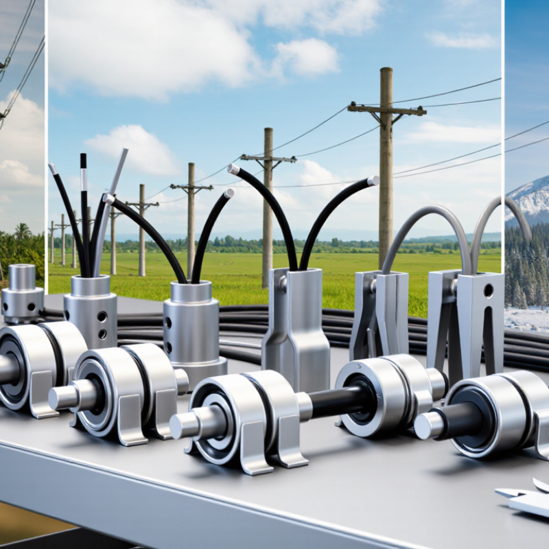
ADSS clamps serve different purposes along an aerial fiber route. Suspension clamps support the cable on intermediate poles, where the line changes direction only slightly. They spread pressure across the sheath and help limit movement in wind. A poorly matched clamp can leave visible marks or allow the cable to slip. Small details matter.
At anchor points, dead-end or tension clamps grip the cable and transfer its pulling force to the pole. They are used at route ends, major turns, and selected span transitions. Downlead clamps secure cable as it runs down a pole, keeping it clear of sharp edges and routine access areas. Each type has a distinct role; substituting one for another can create stress in the wrong place.
Selection depends on cable diameter, span length, expected tension, pole geometry, and local weather exposure. For example, a long, windy span may need a different support arrangement from a short run beneath tree cover. Check the clamp’s stated cable range and installation method against the cable supplier’s specifications. On site, inspect the contact surfaces and confirm that the cable sits evenly. A tidy appearance helps, but it is not proof of correct loading. There is no perfect table for every route; field conditions sometimes reveal what the drawings missed.
| ADSS Clamp Type | Primary Role | Typical Location | Key Selection Factors | Practical Design Notes |
|---|---|---|---|---|
| Suspension Clamp | Supports the cable at intermediate structures while allowing the line to continue along its route. | On poles or towers along a straight or gently changing section of an aerial span. | Cable diameter and construction; span length; cable weight; wind and ice loading; line angle; structure geometry. | Use a clamp designed for the specified ADSS cable. Its contact surfaces should support the cable without cutting, crushing, or excessively bending the outer sheath. |
| Tangent Suspension Clamp | Provides support where the cable passes through a structure with little or no directional change. | Intermediate poles or towers on relatively straight routes. | Manufacturer’s allowable line-angle range; design tension; span conditions; cable size; required support hardware. | “Tangent” describes the installation condition, not a universal load rating. Confirm the permitted angle and mechanical limits in the product and project specifications. |
| Dead-End (Tension) Clamp | Anchors the cable and transfers longitudinal tension to the supporting structure. | Route ends, section ends, major direction changes, and other engineered tension points. | Maximum design tension; span and loading conditions; cable diameter; cable construction; attachment hardware and structure strength. | Select an assembly intended for the specific ADSS cable and load case. Do not substitute a suspension clamp where an anchoring assembly is required. |
| Downlead Clamp | Secures and guides cable along a pole or tower, helping control the vertical cable run. | Vertical transitions between the aerial route and equipment, cabinets, or underground duct entries. | Cable diameter; support spacing; mounting surface; exposure to weather; required bend radius and cable-entry arrangement. | Downlead clamps provide routing support; they are not substitutes for suspension or dead-end clamps. Follow the cable supplier’s minimum bend-radius guidance. |
| Suspension Clamp with Armor Rods | Supports an ADSS cable while distributing contact pressure and helping protect the cable at the support point. | Selected intermediate supports where the cable and project design call for a rod-reinforced suspension assembly. | Compatibility between rods, clamp, and cable; cable diameter; span loading; installation method; specified electrical and mechanical environment. | Armor rods are an accessory used with a compatible support assembly, not a standalone clamp. Use only combinations approved for the cable and installation design. |
Selection note: ADSS clamp requirements vary with cable construction, span, route geometry, wind and ice loads, temperature, and local installation standards. Verify dimensions, allowable loads, line-angle limits, and hardware compatibility against the cable data and project engineering documents before installation.

How to Choose the Right ADSS Clamp for Global Projects?
Verify Cable Outer Diameter, Span Length, and Rated Tensile Strength
Start with the cable’s actual outer diameter, including its outer sheath. Match it to the clamp’s stated diameter range, not a nominal value copied from an old drawing. Check the cable datasheet for manufacturing tolerances, then measure a sample where possible. A clamp that is too loose may slip; one that is too tight can deform the jacket. Measure twice. Span length matters, but it is not a load rating. Wind, ice, line angle, and elevation also affect mechanical loading. The ITU’s Facts and Figures 2023 estimated that 5.4 billion people, or 67% of the world’s population, used the internet. That growth puts more pressure on reliable network builds, but it does not replace site-specific engineering.
Compare the clamp’s rated tensile strength with the cable’s rated tensile strength and the project’s expected working tension. Do not assume that matching two headline ratings is enough: confirm the applicable safety factors and installation limits with the cable documentation and project engineer. IEC 60794-4-20 covers specifications for ADSS optical fibre cables; use the relevant cable test and performance information when checking compatibility. A small field detail can be missed: measure the cable at the intended grip point, where sheath texture or ovality may differ from a neat warehouse sample. Record the diameter, span, support angle, and loading assumptions for each route section. Global projects rarely share identical conditions, and a tidy spreadsheet may still hide a poor fit on the pole.
Verify cable outer diameter, span length, and rated tensile strength before selecting a clamp.
The chart shows illustrative project cases, not product specifications or universal selection limits. Confirm that the clamp’s diameter range matches the cable’s measured outer diameter. Select hardware for the actual span and site conditions using the cable manufacturer’s sag-tension data and the clamp’s rated tensile strength; span length alone does not determine the required rating.
Choosing an ADSS clamp starts with the loads the cable will actually face. Under IEC 60794-4-20, check the cable’s aerial performance requirements, then apply the project’s approved environmental design values. Calculate wind load using the specified wind pressure and the cable’s exposed diameter. Include ice thickness, since ice increases both weight and wind-catching area. Small details matter.
Sag and tension change with span length, temperature, cable weight, and added ice. Use the cable’s documented mechanical data and a suitable sag-tension method to estimate support loads. Then confirm the clamp’s holding capacity, contact pressure, and compatibility with the cable diameter. A clamp that grips too tightly may damage the sheath; one that slips can alter sag. Real site conditions rarely match a neat spreadsheet perfectly, so verify assumptions against route surveys and installation records.
Tips: Record the wind zone, ice thickness, span, and temperature used in each calculation. Check the clamp supplier’s rated limits, and request engineering review when inputs are uncertain. Measure, then verify.
Choosing an ADSS clamp starts with the cable, not the pole. Check the cable’s outside diameter and the clamp’s specified grip range. A loose fit can allow movement; excessive grip may damage the sheath. Match the clamp to the cable maker’s installation guidance and the route’s expected tension.
Bend radius matters most where the route changes direction. At a pole near a road crossing, for example, a sharp turn can press the cable against hardware. Select a clamp arrangement that keeps the cable above its minimum bend radius, with extra clearance where practical. Check transitions, not just straight spans. A smooth-looking route can hide a tight bend behind a bracket.
Wind exposure, long spans, and uneven terrain also affect the choice. Review local loading assumptions and the project design before installation. Then inspect the cable path at each support: look for pinching, sheath marks, and contact with edges. Small field adjustments matter. Yet visual checks alone are not enough; confirm dimensions and loading with qualified project personnel. Real routes are rarely perfectly uniform, and that is worth allowing for.
When selecting an ADSS clamp for a global project, start with the site’s temperature range, not its annual average. A line may face freezing mornings, midday heat, and rapid seasonal swings. Compare the clamp’s operating limits with cable and installation data. Check whether polymer parts maintain grip through repeated thermal cycling. Small details matter.
Corrosion resistance depends on exposure. Coastal salt, industrial deposits, and persistent moisture affect fittings differently. Check material and coating compatibility, especially where dissimilar metals meet; galvanic corrosion is easy to overlook. Stainless hardware is not automatically the right choice. Verify the complete assembly, including fasteners, and request test records relevant to the expected environment. Damaged coating around a bolt can be an early warning, not merely a cosmetic issue. Check the full assembly.
Utility-line clearance needs equally careful review. Confirm separation from energized conductors, structures, and nearby cables using the project’s engineering criteria. Include expected sag, wind movement, and ice loading, rather than measuring only a calm-day span. Clamp dimensions and mounting position can shift the cable path. Leave room for inspection. Clearance reviews sometimes happen too late, though that risk is easy to miss on drawings. If site conditions differ from design assumptions, pause and recheck with the responsible line engineer. A neat fit does not prove safe clearance.