How to Choose the Right CCS Busbar?
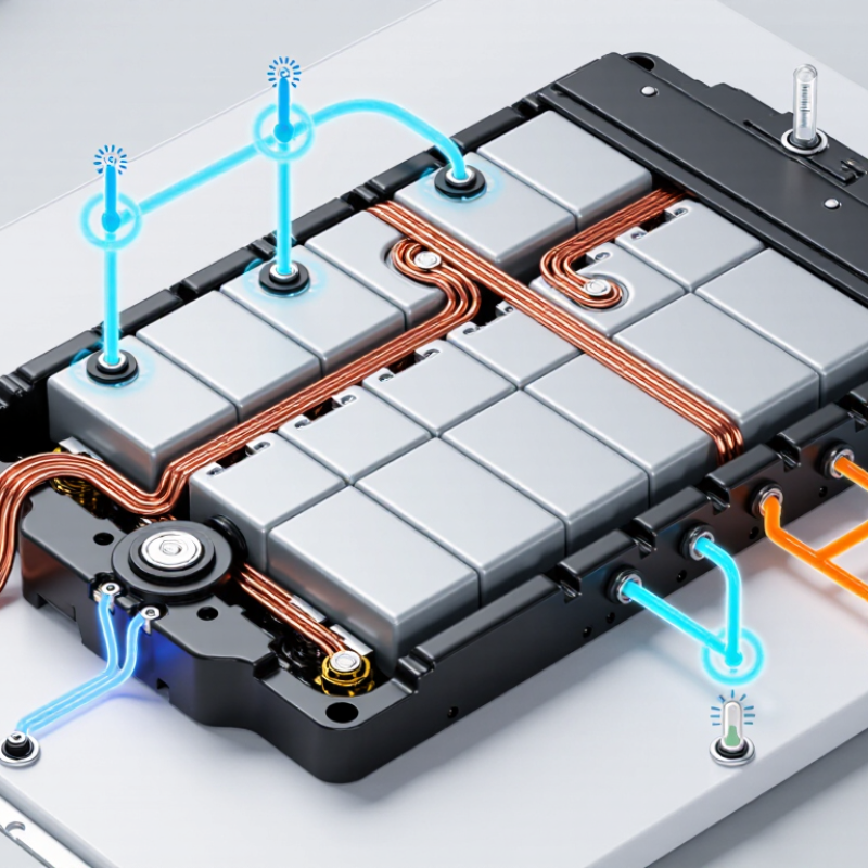
Choosing the right CCS Busbar means matching the connection system to the battery pack, not simply selecting a conductor by appearance. In a cell connection system, busbars link battery cells and may also support voltage sensing and temperature monitoring. Their layout affects electrical performance, assembly, and serviceability.
Start with the pack’s operating requirements. Check nominal and peak current, voltage, allowable temperature rise, and available space. A busbar that looks robust may still create excess resistance at a narrow section or joint. Watch the contact points. Poor alignment or inconsistent welding can undermine an otherwise suitable design.
Material and construction matter, too. Copper offers high conductivity, while aluminum can reduce weight; each brings different joining and thermal considerations. Insulation, creepage distances, vibration exposure, and nearby cooling paths should be reviewed against the actual pack design. Measure the clearances around terminals and cooling plates, not just the drawing dimensions. Small gaps matter.
Reliable selection depends on verified data. Compare supplier specifications with the battery’s duty cycle, manufacturing process, and environmental conditions. Ask how resistance, temperature rise, and joint strength were evaluated, and confirm that test conditions reflect real use. A datasheet alone may not answer every question. That is worth questioning.
This guide explains the main criteria for choosing a CCS Busbar, from electrical sizing and materials to integration and quality checks. It also highlights trade-offs that are easy to overlook. The right choice is application-specific, so final decisions should be reviewed by qualified battery and electrical engineers.
Identify the Battery Pack and CCS Busbar Requirements
How to Choose the Right CCS Busbar?
Identify the Battery Pack and CCS Busbar Requirements
Start with the battery pack, not a catalogue photo. Record cell type, series and parallel configuration, pack voltage, and expected continuous and peak current. These details define electrical and physical requirements. A pack with tight cell spacing may need a different busbar layout than one with room for wider connections. Measure cell terminals, clearances, and mounting points directly. Drawings can be outdated.
Check how the CCS busbar will handle sensing and insulation. Confirm whether the assembly includes voltage-monitoring connections, temperature sensors, or a flexible circuit. Compare terminal materials and plating with the cell specifications. Then review current paths, heat buildup, vibration, and the enclosure’s operating temperature. A busbar that fits on paper may still interfere with a cover or cooling channel. I have learned that one overlooked connector can complicate assembly.
Tips: Keep a simple requirements sheet with dimensions, current limits, sensor locations, and insulation needs. Measure twice. Ask the pack engineer to verify uncertain values before ordering. Do not guess. If the battery layout is still changing, mark the drawing as provisional and recheck it against a physical sample.
How to Choose the Right CCS Busbar: Identify the Battery Pack Requirements
Representative nominal cell voltage by chemistry
Nominal cell voltage helps estimate pack voltage: multiply it by the number of cells connected in series. These values are representative, not specifications for every cell. Before designing a cell contact system (CCS) busbar, check the selected cell’s datasheet and pack layout, then define the required current, temperature range, insulation clearances, and connection geometry.
Calculate Current Capacity and Electrical Performance
A CCS busbar should be sized for the charger’s real operating current, not just its headline power. Estimate current with I = P ÷ V, using the lowest expected DC output voltage for a conservative check.
For example, a 150 kW output at 500 V requires about 300 A. Leave room for continuous operation and brief peaks.
Check the busbar’s rated capacity against its material, cross-section, length, and cooling conditions. A conductor inside a warm, crowded cabinet may carry less current than the same part in open air. Small details matter.
Estimate voltage drop from current and resistance; resistance rises as copper heats, so include operating temperature in the calculation. Inspect joint design, too. A slightly loose connection can create a hot spot, even when the busbar itself is adequately sized.
Measure temperature and voltage drop under representative load before finalizing the design. Calculations are useful, but installation conditions can still surprise you. I would revisit assumptions if the cabinet layout or charging duty changes.
Select Conductor Materials and Busbar Geometry
Choose the conductor material from the busbar’s actual operating conditions, not current rating alone. Copper offers high conductivity and compact dimensions, which can help where space is tight. Aluminum is lighter, but usually needs more cross-sectional area for comparable electrical performance. Its contact surfaces also require careful joint design because oxide layers can affect connection quality. Check peak current, duty cycle, ambient temperature, cooling, and allowable voltage drop before settling on either material. Heat matters.
Geometry determines how that material performs inside the assembly. A wider, thinner bar may fit a low-profile space, while a thicker section can provide stiffness. Neither shape is automatically better. Avoid narrow necks and abrupt bends near high-current paths; these details can concentrate heat or complicate forming. Keep adequate clearance from nearby conductors and enclosure walls, and give fasteners enough room for reliable contact. A drawing alone can mislead. Build a representative sample and measure temperature rise at joints and bends under realistic load. If the first layout runs warmer than expected, revise the shape or connection before freezing the design. There is rarely one perfect geometry; packaging, cooling, manufacturing, and service access all matter.
Evaluate Insulation, Thermal, and Mechanical Requirements
Choosing a CCS busbar starts with the real duty cycle, not the headline current. IEA’s Global EV Outlook 2024 reports that public charging points grew by over 40% in 2023. Fast chargers grew by 55%. These figures show rising infrastructure demand, but they do not set a busbar’s rating. Use measured peak load, ambient temperature, enclosure airflow, and simultaneous charging conditions. Small details matter.
For insulation, check working voltage, transient conditions, pollution level, and required clearance and creepage distances against the applicable equipment standard. A clean cabinet can still collect conductive dust after months of fan operation. Confirm the insulation system’s temperature rating and inspect spacing after assembly, not only in a CAD model. Thermally, calculate continuous current at the highest expected ambient temperature. Include terminal contact resistance. Then test temperature rise under sustained load; a loose joint may heat locally before the busbar shows obvious stress.
Mechanical checks are easy to underweight. Assess short-circuit forces, vibration, support spacing, and fastener retention. IEC 61439-1 covers assembly verification, while IEC 61851-1 addresses EV supply equipment; confirm which requirements apply to the specific design. Keep test records tied to the exact conductor material, plating, and fastener stack. A prototype test can reveal problems that calculations miss.
Verify System Compatibility, Safety, and Quality Testing
Choosing a CCS busbar starts with the actual system, not a catalogue current rating. Check DC voltage, continuous and peak current, fault level, enclosure space, and terminal geometry against the charger design. A bar that fits mechanically may still create a hot joint if contact pressure or plating is unsuitable. The IEA’s Global EV Outlook 2024 reports that public charging-point numbers grew by more than 40% in 2023, increasing pressure on operators to build dependable equipment. Growth is not a reason to skip verification.
Safety depends on the complete assembly. Confirm insulation, clearances, creepage distances, earthing, and temperature limits under the expected load and ambient conditions. IEC 61851 and IEC 61439 offer relevant charging-system and switchgear frameworks; confirm which requirements apply to the specific assembly. Ask for traceable material certificates and test records, not just a pass statement. Useful checks include dielectric withstand, temperature rise, short-circuit performance, and vibration where the installation demands it. Measure temperature at joints during sustained full-load testing. Small details matter.
A drawing review can catch misaligned terminals before installation. Yet test conditions should match real cable routing and cooling; a laboratory setup may be kinder than a crowded cabinet. I would also review inspection criteria after thermal cycling. That step is easy to overlook.